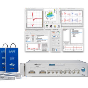
IPA® / DOUBLE IPA®
Integrated Patch Clamp Amplifiers with Data Acquisition System
Sutter Instrument introduces the IPA® family of Integrated Patch Amplifiers, which enables efficient, low-noise whole-cell recordings. The IPA systems, available in either a single headstage (IPA) or dual headstage (DOUBLE IPA) version, combine state-of-the-art amplifier technology with fully integrated D/A and A/D conversion and a high speed USB interface.
Product Enquiry
If you would like to send us an enquiry about this product, please click the button below, fill in the form and submit.
Product Enquiry
Product Enquiry
Please fill out the form if you would like to enquire about this product."*" indicates required fields
Sutter Instrument introduces the IPA® family of Integrated Patch Clamp Amplifiers, which enables efficient, low-noise whole-cell recordings. The IPA systems, available in either a single headstage (IPA) or dual headstage (DOUBLE IPA) version, combine state-of-the-art amplifier technology with fully integrated D/A and A/D conversion and a high speed USB interface. Acquisition, data management, and streamlined analysis are performed using the bundled SutterPatch® Data Acquisition and Analysis Software, built on the foundation of Igor Pro (WaveMetrics, Inc.).
External Inputs & Outputs
4 auxiliary analog input channels enable external signals, such as environmental parameters or stimulus information to be recorded. The IPA systems also support the control of peripheral hardware, such as wavelength or solution switchers, with 2 analog and 8 digital (TTL) output channels. As an alternative to the standard breakout cable, an optional Patch Panel provides a tidy way of connecting auxiliary signals on the front of your rack.
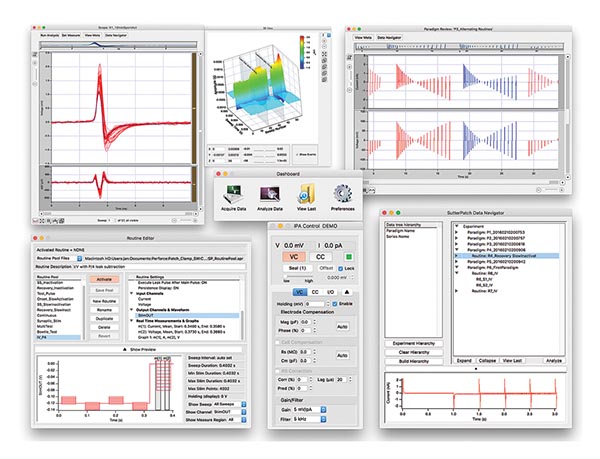
SutterPatch Software
The IPA system, in combination with SutterPatch software, has been engineered to automatically capture and store all amplifier settings, stimulus information and external experiment parameters and associate them in time with the raw data traces. This includes all amplifier and acquisition settings, as well as timing and progress of the experiment. Fully integrated computer control of the amplifier stages means that the acquisition software is aware of the internal state of the amplifier and digitizer at all times and can track any changes that may occur. This is independent of whether a change is triggered automatically or initiated by the user.
Tracking of Other External Data
In addition to status changes in connected hardware that are automatically tracked, the experimenter can manually trigger tags to document events like stimulus application in instruments not connected to the IPA system.
Information about environmental parameters and a more detailed specification of sample properties can be recorded and stored with the raw data. A total of over 600 metadata attributes are supported. Examples include: animal species, strain, genotype, date/time when a cell sample was prepared, recording solutions, pipette resistance, hardware properties, and detailed information about stimuli applied.
Data Visualization and Analysis
SutterPatch software has been designed to simplify the navigation and analysis of complex datasets. The scope window supports multiple view modes in both two-dimensional and an innovative three-dimensional display. The 3D view is particularly useful during assay development. Built on top of the latest version of the proven Igor Pro platform, the SutterPatch program combines native Igor Pro functionality with a wealth of features that are tailored to electrophysiology applications. Both the newcomer and experienced user of patch clamp programs will feel comfortable using SutterPatch software.
Application modules provide focused functionality for particular applications.
Currently available:
- Event Detection Module: A deconvolution algorithm that excels at detecting miniature synaptic events even on a noisy background
- Action Potential Analysis Module: Phase plane plot, timing and waveform statistics
- Camera Module: An easy way to document the identity and condition of the recorded cell
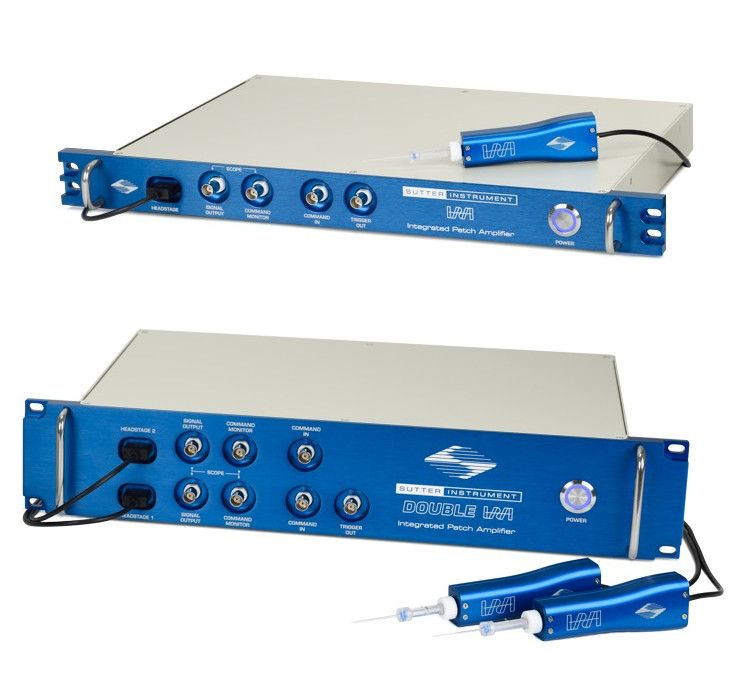
The IPA and Double IPA Integrated Patch Clamp Amplifiers are computer-controlled single- or dual-headstage amplifiers optimized for whole-cell recording applications.
Common Applications
| Tissue slice recordings | In-vivo patch clamp |
| Cultured-cell experiments | Network studies |
| Cell line studies from adherent or dispersed cells | Optogenetics |
Features
- NEW: Combination of any two IPA or Double IPA devices enables up to four headstage channels for as many as 16 signals
- Fully integrated patch clamp amplifier and data acquisition system ensures quick and easy setup
- Optimized for whole-cell patch clamp recordings in tissue slices, adherent or dissociated cells
- Full computer control provides automated compensation of electrode and whole cell capacitance
- Voltage and current clamp capability for complete characterization of cells’ electrical activity
- Bundled SutterPatch software excels in comprehensive data management, intuitive navigation and streamlined data analysis
- Line frequency reduction in SutterPatch
Accessories
Optional IPA Patch Panel
The IPA and Double IPA Amplifiers come standard with an “octopus” breakout cable for auxiliary inputs and outputs, and digital outputs. The optional IPA Patch Panel, machined from ½” thick billet aluminum stock like the IPA faceplate, brings the auxiliary I/O connections to the front of the rack in a tidy 2U rack mount panel with BNC connectors. The IPA Patch Panel includes a 2.5 ft (76 cm) connector cable and replaces the standard cable that ships with the IPA system.

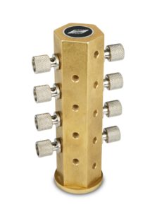
Ground Point
The Ground Point GP-17 provides reliable, low resistance connections for star ground connections, the proven method to avoid ground loops in any electrophysiology setup. Accepts 9 banana plugs + 8 bare wires up to 10 gauge or banana plugs. The baseplate mounts directly on standard or metric air table tops with the included ¼-20 and M6 screws. Made of solid, machined brass with plated banana/clamp connectors.
Ordering Information
| Catalog Number | Description |
| IPA | Includes: IPA system with headstage, EH-P170 pipette holder, model cell, “octopus” breakout cable, rack mounting hardware; SutterPatch® software suite with Igor Pro license |
| IPA-2 | Includes: Double IPA system with two headstages, two EH-P170 pipette holders, model cell, “octopus” breakout cable, rack mounting hardware; SutterPatch® software suite with Igor Pro license, |
Accessories
| Catalog Number | Description |
| IPA-PCH | Patch panel with 8 digital out / 4 aux. in / 2 aux. out |
| GP-17 | Ground point, accepts banana plugs and clamp wires up to 10 gauge |
| RACK-PK | Rack mounting hardware |
Pipette Holders
While polycarbonate is a proven material for patch pipette holders, it undergoes significant thermal expansion. Uneven warming may lead to motion of the pipette tip and is often incorrectly perceived as drift in the micromanipulator. Quartz has a significantly lower thermal expansion coefficient and virtually eliminates thermal drift. (Link to video: Minimizing thermal expansion with the Sutter Instrument Quartz Pipette Holder)
Note: Quartz is fragile and may crack or shatter on impact. Treat your quartz electrode holder with the same care you would with any optical component.
| EH-P170 | Polycarbonate pipette holder 1.0-1.7 mm O.D. |
| EH-Q170 | Quartz pipette holder 1.0-1.7 mm O.D. |
Technical Information and Videos
User Manuals
IPA & SutterPatch Quick Start Guide
IPA & SutterPatch Operation Manual
Product Information
IPA / DOUBLE IPA Sales Flyer: English / Chinese
SutterPatch Sales Flyer
Comparison of Sutter Amplifier Systems
SutterPatch Informational Video
Minimizing thermal expansion with the Sutter Instrument Quartz Pipette Holder
Experiments of interest involving the IPA Family of Integrated Patch Amplifier Systems
Videos
SutterPatch Informational Video
Minimizing thermal expansion with the Sutter Instrument Quartz Pipette Holder
SutterPatch Walk-Through: #1 Introduction
SutterPatch Walk-Through: #2 Amplifier Control
SutterPatch Walk-Through: #3 Routines
SutterPatch Walk-Through: #4 Data Navigator and Metadata
SutterPatch Walk-Through: #5 Application Modules
Amplifier
- Voltage clamp and true current clamp modes with smart switching between modes to avoid current artifacts
- Open-Circuit (RMS) noise of 1.4 pA in a 0.1-10 kHz bandwidth
- 500 MΩ headstage feedback resistor provides a max. range of ±20 nA
- Fast pipette capacitance compensation and whole-cell compensation
- Pipette capacitance compensation up to 25 pF
- Whole-cell compensation: Cm from 1-100 pF ; Rs from 1-100 MΩ
- Onboard automatic compensation routines
- Series resistance prediction and correction (0-100 MΩ)
- Four-pole Bessel low-pass filter (cutoff = 0.5 – 20 kHz)
- Output gain: 0.5-25 mV/pA (voltage clamp); 10-500 mV/mV (current clamp)
- Holding potential ±1000 mV
- Current clamp bridge compensation and capacitance neutralization
- Slow holding potential tracking compensates for drift during current clamp recordings
Data Acquisition
- Embedded data acquisition system eliminates the need for an external data acquisition board and facilitates setup
- Single high-speed USB connection controls data acquisition and amplifier
- Up to 6 or 8 input channels (0.1 – 50 kHz sampling rate per channel)
- Up to 400 kHz aggregate sampling rate
- Multi-amplifier mode: A combination of any two IPA or Double IPA Amplifiers can be connected, providing up to 16 input channels
- Complex command waveforms
- Auxiliary input / output for control of other instrumentation
- 4 analog input channels (±10 V)
- 2 analog output channels (±10 V)
- 8 digital output channels (TTL)
- Data acquisition can be initiated by an onboard microsecond clock or external (TTL) trigger
Dimensions
IPA®: 18.8 in x 11.8 in x 1.8 in | 48 cm x 30 cm x 4.5 cm
DOUBLE IPA®: 18.8 in x 11.8 in x 3.5 in | 48 cm x 30 cm x 9 cm
Patch Panel: 18.8 in x 2 in x 3.5 in | 48 cm x 5 cm x 9 cm
Weight
IPA: 9 lbs | 4 kg
DOUBLE IPA: 8.1 lbs | 3.7 kg
Patch Panel: 3.5 lbs | 1.6 kg
Electrical
110/240 Volts
50/60 Hertz power line
SutterPatch® Software
- Built on the foundation of Igor Pro (WaveMetrics, Inc.)
- Paradigms and Routines provide complete experimental control
- Waveform Editor for easy creation of even the most complex stimulus patterns or user-defined templates
- Associated metadata stores all relevant information regarding your experiment
- Comprehensive data analysis routines and publication quality graphics
- Runs on Windows 10 or later (64-bit) or Mac OS X 10.11 (El Capitan) or later
System Requirements
Minimum Configuration:
- Operating System: Windows 10 (64-bit) or later, or MacOS: 10.11, El Capitan or later
- Processor: Dual-core i5
- Memory: 3 GB
- Hard Disk: 500 GB or greater
- Display Resolution: 1024 x 768 (XGA)
- 1 available USB 2.0 High Speed port
Recommended Configuration:
- Windows 10 (64-bit) or later, or MacOS: 10.11, El Capitan or later
- Processor: Dual-core i5
- Memory: 8 GB
- Solid-state drive (SSD), 500 GB or greater
- Display Resolution: 1920 x 1080 (FULL HD)
- 1 available USB 2.0 High Speed port
Notes:
USB 3.0 ports are compatible with USB 2.0 High Speed specifications.
Slower USB 2.0 ‘full-speed’ ports, which are sometimes found on older Windows PCs or USB add-in cards, are not supported.
To check for High Speed USB 2.0 or USB 3.0 on a PC computer running Windows, look in the Control Panel > Device Manager > Universal Serial Bus controllers section for “Enhanced” host controllers. As this does not provide any mapping information to the computer’s physical ports, and there can be a mix of USB port versions, you should check individual USB ports for USB 2.0/3.0 High Speed operational performance. As a visual indicator, USB 3.0 ports are often color coded blue.
USB hubs are not supported. USB add-in cards, even if they formally meet High Speed or Super Speed specifications, are not recommended. They are often architecturally configured as USB hubs and may lead to intermittent transfer errors that are hard to troubleshoot.
Operating systems installed within virtualization software platforms such as VMware and Parallels are not supported