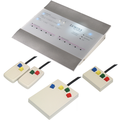
Lumina Response Pads for fMRI
Lumina is a quality-built patient response system (also called button response unit, or BRU) designed for use in an MRI environment. It meets the requirements of both the clinical and research communities.
For maximum patient safety, the response pads are built with 100% plastic and fiber optics, eliminating all risk to patients and all interference with or from the magnet.
Product Enquiry
If you would like to send us an enquiry about this product, please click the button below, fill in the form and submit.
Product Enquiry
Product Enquiry
Please fill out the form if you would like to enquire about this product."*" indicates required fields
![]()
Reliable, Accurate, and Safe
Lumina is a quality-built patient response system (also called button response unit, or BRU) designed for use in an MRI environment. It meets the requirements of both the clinical and research communities.
For maximum patient safety, the response pads are built with 100% plastic and fiber optics, eliminating all risk to patients and all interference with or from the magnet.
Key Layouts for Different Applications
 |
LS-PAIR |
 |
LS-3B |
 |
LS-DIAM |
 |
LS-RH |
 |
LS-THUMB |
 |
LS-LINE |
Stimulus Types
Lumina’s sturdy and fast controller captures patients’ button presses and the triggers generated by MR scanners, time-stamps them with a millisecond accuracy, and converts them into simultaneous USB port and parallel outputs*.
The controller is supported by many software packages and programming languages (see below).
* Time-stamped information is output only on the USB port
Trusted By The World’s Best Companies
We take great pride in being the exclusive button response unit (BRU) supplier to the world’s premier suppliers of MRI accessories. There is no greater endorsement or compliment.
Extensive Software Support
Applications |
|
| SuperLab Published by Cedrus; built-in support |
EyeLink Experiment Builder Built-in support |
| E-Prime Controller emulates a PST Serial Response Box |
Presentation Cedrus provides a plug-in for Presentation |
| MEDx By Medical Numerics; built-in support |
Inquisit Built-in support |
| VSG By Cambridge Research Systems; built-in support |
Paradigm By Perception Research Systems |
| PsyToolkit Linux open source library by Dr. Gijsbert Stoet |
Libraries |
| The commands that the Lumina controller accepts are public. Cedrus publishes and maintains Python and C++ code libraries. |
Premium Warranty Available
Lumina systems are covered by a one year standard warranty. We also offer a premium warranty for more peace mind that includes:
Longer Coverage
Three times longer, to be exact. Your system is covered for a full three years instead of one.
Immediate Replacement
Should your system break down for any reason, Cedrus will send you a replacement unit immediately that you can use until your unit is repaired.
The Lumina 3G Controller
Mighty Power Under the Sleek Hood

Features At a Glance
| Up to 10 Keys Use two response pads simultaneously, with up to five keys each. |
|
 |
Sync With Scanner Compatible with GE, Siemens, and Phillips MRI scanner triggers |
 |
Universal Software Support USB “keyboard mode” makes your controller work with any software package. |
| Built-In I/O It’s like getting a free I/O device that can send 8 bits of TTL output. |
|
 |
Millisecond Timing Built-in high resolution timer that can be reset in three different ways. |
 |
Light Sensor Support Record precisely the onset of visual stimuli and even have it reset the built-in timer. |
Most Compatible
Keyboard Mode
With this feature, your computer thinks that a second USB keyboard is plugged in, allowing the controller to work with any software.
Broad Application Support
A number of software packages know how to communicate directly with the Lumina controller and take advantage of its features:
- SuperLab
- Inquisit
- E-Prime
- MEDx
- Presentation
- VSG
- Experiment Builder
Libraries
The commands that the Lumina controller accepts are public. Cedrus publishes and maintains Python and C++ code libraries.
Accuracy By Design
The built-in timer in the Lumina controller measures with precision when the participant presses (or releases) a key, then sends time-stamped information to the computer.
Just as important, the timer can be reset in one of three ways: via a command sent over USB, when the light sensor detects the onset of a visual stimulus, or via an external device.
Well Connected

Frequently Asked Questions (FAQs)
How is a Lumina response pad system installed?
A Lumina system consists of several parts, some installed inside the fMRI magnet room and some outside:

A: Response pads, built of 100% plastic and fiber optics, safe to use by patients inside the bore of the magnet.
B: OTEC unit, converts electricity to light, is connected to the pads via 5.5m (16ft) of fiber optic cables.
C: Shielded cable, about 21m (65ft) long, connects the penetration panel to the Lumina controller.
D: Preexisting penetration panel, needs to have an available DB9 cutout. See the Accessories page if you do not have such a cutout and need a replacement panel plate.
E: RF filter, available from Cedrus at no cost if your penetration panel does not have a built-in filter.
F: Shielded cable, about 21m (65ft) long, connects the OTEC unit to the penetration panel.
G: Controller, detects button presses, scanner trigger input (not shown in diagram), and provides simultaneous USB and digital output.
H: USB cable, connects controller to your stimulus presentation computer.
Though not shown in the diagram, you can also connect the scanner trigger to the Lumina controller, which in turn forwards that information to its USB port and its Accessory Connector.
Can I use more than one set of pads?
Yes. This requires two each of parts A, B, C, and E, plus a low-cost Copper Outpost. The outpost is a signal multiplexer that allows two OTEC units (B) to become “visible” to the controller.

Specifications of the Lumina 3G Controller
USB
The USB port can operate in one of two modes: Keyboard or Standard:
- In Keyboard mode (also known as HID mode), your computer “sees” the controller as a keyboard, making it possible for any program to handle the controller’s output. Key press and scanner triggers can be sent to computer in different preset formats, selected from the front panel. No driver installation is necessary.
- In Standard mode, your computer “sees” a device that is connected as a serial communications port. It is supported by several programs like SuperLab, E-Prime, Presentation, Inquisit, and others; C++ and Python libraries are also available. Several protocols (data formats) are supported and can be selected from the front panel. Supported baud rates are 115200, 57600, 19200, and 9600.
Timing
- Time from button press to having a signal out (on Accessory Connector and USB ports): less than 500μs.
- Time from scanner trigger input to having a signal out: less than 10 μs.
- Typical USB driver delay when controller is in Keyboard mode: up to 10 milliseconds.
- Typical USB driver delay when controller is in USB Standard mode: 5 to 16 milliseconds.
- Light sensor latency: less than 10 μs. This is the latency of the Lumina controller only; see below for the light sensor’s response time.
To get around delays inherent in USB drivers, the controller can send time-stamped information in both Keyboard and USB Serial modes. The timer can be reset via a light sensor or an external TTL signal. In USB Serial mode, the timer can also be reset via a command sent over USB.
Trigger Input
The controller provides two methods for accepting triggers from fMRI scanners:
- Fiber optic, suitable for Siemens scanners. Minimum pulse duration is 5μs.
- Electrical, suitable for GE and Phillips scanners. Minimum pulse duration is 5μs. This input accepts both TTL and differential voltage signals.
For maximum safety, the electrical trigger input can be optically isolated, guaranteeing that no unwanted electricity flows between the controller and your MRI scanner. When optically isolated, the input needs nominal 5mA and a minimum of 1mA. The input has a 100 Ohm resistor to limit the current to about 30mA if the source is not current limited. When not optically isolated, the connector sources current from 5V through a 1k resistor so the driver needs to sink 5mA.
Accessory Connector II
When used in conjunction with other Cedrus products such as m-pod (and depending on their availability), the following signals are available on Accessory Connector II:
- 5 parallel output lines (TTL) to indicate button presses on response pad 1
- An OR’d output line that is active when any button is pressed on response pad 1
- An OR’d output line that is active when any button is pressed on response pad 2
- 3 lines to indicate when light sensor detects light, timer is reset, or an fMRI trigger is received
- 8 general purpose TTL output lines that can be controlled from computer
- 8 general purpose TTL input lines
- External input to reset built-in timer
- RS-232 serial output
To make all these data signals available while still using a small connector, the data lines are multiplexed and require some electronics to demultiplex them. They are not readily useable. The timer reset line is not multiplexed.
Serial Port
Serial input/output signals are available on Accessory Connector II and are not multiplexed. An m-pod is needed to convert the signals to RS-232 levels, the standard that is used in computers’ serial ports. m-pod also provides a standard DB9 connector. Supported baud rates are 115200, 57600, 19200, and 9600.
Firmware
XID, or eXperimental Interface Device, is technology first used by Cedrus in 2001 on Lumina’s first generation controller and later adopted on all Cedrus hardware products. The current 3G Lumina controller’s firmware implements the XID 2.0 platform. The firmware is upgradeable.
Power Requirements
The Lumina controller ships with a medically rated, UL-60601 certified AC adapter. It accepts 100-240VAC, 50-60Hz input, and produces regulated 9VDC, 2.0A max. CE certified. See Accessories page for more information.
Copper Outpost
The optional Copper Outpost allows the Lumina controller to recognize two Lumina response pad sets instead of just one, allowing for a maximum of eight buttons.
The Copper Outpost can sit on a desk or be wall mounted. Its power is provided by the controller; no separate AC adapter is needed.
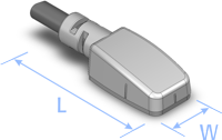
Cedrus Light Sensor
The Cedrus Light Sensor allows the Lumina controller’s built-in timer to be reset without delay — useful when taking advantage of the controller’s time stamping feature. It is available in two colors: black and white. Notches are molded in on three sides to allow for easy positioning on the screen.
Characteristics
| Response time (dark to light) | 0.05 milliseconds |
| Release time (light to dark) | 4 milliseconds |
| Spectral sensitivity | 360-970 nm (visible light) |
The response and release times are dependent on the amount of light.
Dimensions
The Cedrus light sensor is small, measuring a mere 8mm (W) by 20mm (L) including the wire’s strain relief (8 by 14mm without it).