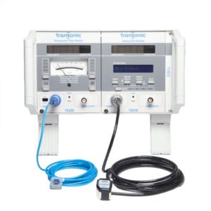
TS410 Tubing Flow Module
Precision Volume Flow Measurements for In Vitro and Extracorporeal Tubing
Product Enquiry
If you would like to send us an enquiry about this product, please click the button below, fill in the form and submit.
Product Enquiry
Product Enquiry
Please fill out the form if you would like to enquire about this product."*" indicates required fields
![]()
Precision Volume Flow Measurements for In Vitro and Extracorporeal Tubing
Whether in the animal lab or in the R & D engineering suite, Transonic’s TS410 Tubing Flow Module gives precision volume flow measurements in tubing with user friendly features applicable to laboratory bench settings, in vitro and extracorporeal use. Two Tubing Flowsensor styles in multiple sizes from 1.2 mm ID to 25.4 mm ID offer versatile functionality to fit every flow circuit application including:
- Circulatory support device development
- Isolated heart and perfused organ studies
- Mock circulatory models
- Flow phantoms
- Any experimental or process application where flow measurement in tubing is needed
Transonic® TS410 Tubing Flow Modules fit into 400-Series Instrumentation Consoles and are compatible to mix and match with other 400-Series Modules.
Product Overview
- Measure True Volume Flow in Tubing
- Measures Blood, Saline, Water, Cell Culture, Physiological Buffer Solutions, Blood Analogs such as Glycerine/Water Solutions
- Program Alarm Conditions:
- High / Low Flow Threshold Alarm
- Bubble / “Received Signal” Alarm
- Recalibrate Flowsensors onsite for changed or new parameters (or conditions)
- Compatible with PXL Clamp-on Flowsensors and PXN Inline Flowsensors
- Analog output compatible with most Data Acquisition Systems
- Gold Standard Transit-time Technology
- Installs in a 400-Series Instrumentation Console: T402 or T403
- Not for use in humans
Applications
Transonic® flow meters and Tubing flow sensors provide the necessary flow metrics to test device prototypes and validate pump accuracy, characterize pulsatile and steady flow dynamics, evaluate mechanical heart valve leakage and can monitor flow in just about any flexible tubing circuit from biomedical research applications to pharma bioprocess and bioreactors.
Transonic offers two flow sensor options for measuring volume flow in flexible tubing:
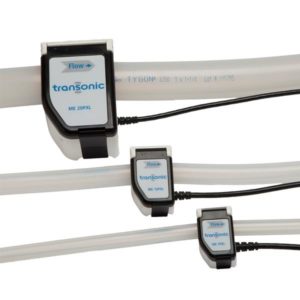
- Clamp-on flow sensors attach to the outside of the tubing so they do not interrupt the flow or sterility of the system. A single flow sensor can be moved between various positions in the system or various systems without having to alter the tubing set-up. However, for best results, the flow sensor should be re-zeroed every time it is repositioned. Clamp-on flow sensors are calibrated for up to four specific tubing, temperature and fluid combinations.
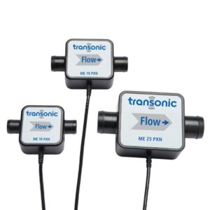
- Inline flow sensors splice into the tubing line with minimal impact on flow behavior. They have the advantage of higher accuracy than Clamp-on flow sensors, especially at low flows. Inline flow sensors are calibrated for up to four combinations of temperature and fluid, being independent of tubing type.
Support Documents
TTU VOLUME FLOW: TS410 Tubing Flow Module Specifications
TTU VOLUME FLOW Tubing Flowsensors
TTU VOLUME FLOW TECH NOTE: Keys to Accurate Tubing Flow Measurement
General Features
Size: 5.125” h x 4” w x 9.062” d
Weight: 2.3 lbs.
Module fits 2 Console slots (20HP) in T402 or T403 Consoles
Power: Derives input power from Transonic® 400-Series Consoles. Installation in a Console is required.
Operational Technology
Ultrasonic Transit-time
Flowsensor Compatibility
ME-PXL- & ME-PXN-Series
Sensor Connector
Front panel 16-pin connector. Accepts research Inline and Clamp-on Flowsensors and extension cables with male CC16 or CP16 connectors.
Automatic Adjustments
Sensor size identification and corresponding flow output ranges. Volume flow calibration and serial number displayed of active Flowsensor.
Digital Display
4-Digit (14 segment) LED displays Flow / Sensor data / Error Messages
Bar Indicator Light: Displays received signal for continuous monitoring of Sensor signal quality.
LCD Display
One line 16-character alpha numeric LCD displays program parameters, Sensor and Meter status, alarm settings. Default displays Sensor serial number.
Set-up/Status & Program Parameters
Status Mode: (White labels)
Status message displayed on LCD.
Sensor Status: sensor type & calibration
Meter Status: Active flowmeter settings & alarm status
Alarm Mute: Audible alarm On/Off
Program Mode: (Blue labels)
Sensor Controls: Select pre-programmed factory calibration options; Adjust Flowsensor gain to change calibration on-site.
1/4 Flow Scale: increases flow gain by factor of 4 for low flow measurements.
Calibrate Scale: sets output to 0 and 1 Volt to calibrate external recording devices with scale factor flow.
Invert flow: inverts polarity of analog outputs & flow display
Alarms Menu: 3 level program to select, set thresholds, and activate Alarms for “Low Flow”, “High Flow” and “Received Signal” Interruption
Filter Properties
0.1, 10, 40 Hz: 2nd order Butterworth, with a third passive pole at 160 Hz
160 Hz: 3rd order Butterworth
Zero Flow Adjust
Recessed momentary push button to zero flow reading at stopped flow.
Flow Output
Front panel mounted BNC output connector & rear panel terminal block:
Pulsatile/Average Volume Flow
Filtering controlled by front panel selectable filters
Voltage range: -5 to + 5 volts
Output resistance: 500 Ohm
Full Range for Flow: -5 to +5 V (bidirectional flows, with range of 5 x scale factor flow)
Automatic Digital Sensor ID & Calibration
TS410 reads operational data (size, scale & calibration) programmed in the sensor’s EPROM.
Ultrasonic Frequency Range
600 KHz to 14.4 MHz; Sensor size dependent
Signal Outputs
8 accessible signals via 400-Series Flowmeter Console’s back-panel terminal block: Pulsatile Volume Flow; Mean Volume Flow; Received Signal Amplitude (2); Phase (4)
Synchronization
Rear panel jumpers select synchronization mode
Self-Triggering Mode: “SYNC IN” to “SYNC OUT” jumper on each Module
Sequential Triggering Mode: “SYNC IN” crossed to “SYNC OUT” between Modules